Update 2015-04-22:
The latest kernel does not use the ads7846_device module any more but uses device tree configuration instead. The instructions are now updated accordingly, thank you to Lauri Anttila for reporting this.
Backstory
One evening I was browsing around ebay.com and came across these pretty cheap less than $30 (including postage) LCD touch screens for Raspberry Pi. I happen to have one Raspberry Pi B+ lying around that didn't work that well in its original intention, but I have had some plans to repurpose it as a controlling device for solar panel charging and electricity in our summer house. A small touch screen would fit that purpose quite nicely, so let's order one of these and try it out first.
TL;DR
I got it working as the main screen in both portrait and landscape mode, the configuration I use for landscape is as follows:
    Update firmware with:
    sudo REPO_URI=https://github.com/notro/rpi-firmware rpi-update

    Enable SPI in raspi-config.

    /etc/modules:
    flexfb nobacklight regwidth=16 init=-1,0xb0,0x0,-1,0x11,-2,250,-1,0x3A,0x55,-1,0xC2,0x44,-1,0xC5,0x00,0x00,0x00,0x00,-1,0xE0,0x0F,0x1F,0x1C,0x0C,0x0F,0x08,0x48,0x98,0x37,0x0A,0x13,0x04,0x11,0x0D,0x00,-1,0xE1,0x0F,0x32,0x2E,0x0B,0x0D,0x05,0x47,0x75,0x37,0x06,0x10,0x03,0x24,0x20,0x00,-1,0xE2,0x0F,0x32,0x2E,0x0B,0x0D,0x05,0x47,0x75,0x37,0x06,0x10,0x03,0x24,0x20,0x00,-1,0x36,0x28,-1,0x11,-1,0x29,-3 width=480 height=320
    fbtft_device name=flexfb speed=16000000 gpios=reset:25,dc:24

    /boot/cmdline.txt:
    add: fbcon=map:1 fbcon=font:ProFont6x11

    /usr/share/X11/xorg.conf.d/99-fbturbo.conf:
    change fb0 to fb1

    /boot/config.txt
    add line: dtoverlay=ads7846,speed=500000,penirq=17,swapxy=1

    /usr/share/X11/xorg.conf.d/99-calibration.conf:
    Section "InputClass"
            Identifier      "calibration"
            MatchProduct    "ADS7846 Touchscreen"
            Option  "Calibration"   "3900 240 240 3900"
    EndSection
Assembly Line
The package arrived from Hong Kong and it contained an LCD module, some pieces of plastic, heatsinks and a DVD with no instruction manual whatsoever.
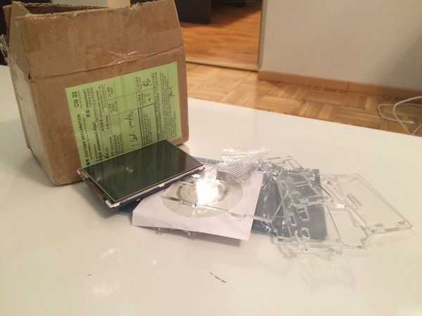 This is what I got in the box...
Well, you get what you pay for and with this price it seems reasonable, so let's just get assembling. After several attempts I finally got the thing into a respectable state, which actually looks pretty nice!
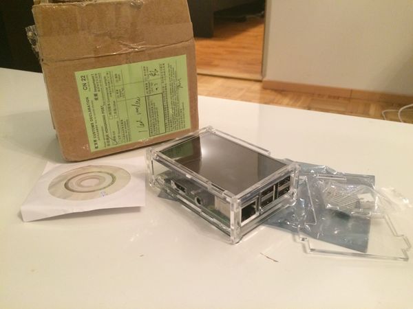 ...and this is how it looks like after completing the puzzle.
At this point I'm all excited to get this running, right? So I go to the official download site, download the latest Raspbian image (which is quite widely supported) and copy it to my SD card. After getting the keyboard, network, HDMI and power wires connected, the device boots very nicely and greets us with the usual Raspbian configuration screen.
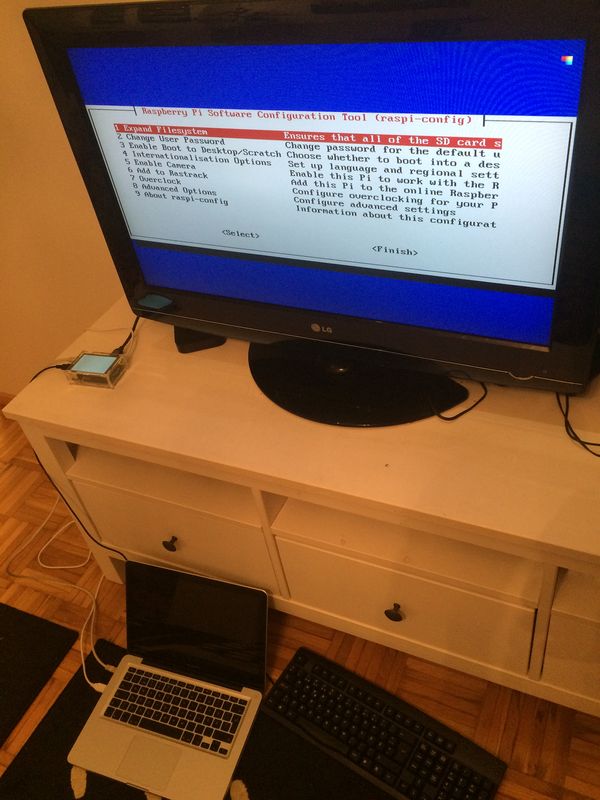 First boot of the system with two screens.
I do the usual routine of expanding disk size, changing password, setting locale and keyboard map, but at the same time I feel a bit nervous, because my fancy new screen stays all white...
Using LCD Responsibly
Now that we have everything set up but the screen doesn't show anything, more problems come up. When I try to fit the small DVD that came with the device to my Macbook Pro DVD drive, it just doesn't fit there (or rather fits too deep), so I have no drivers or instructions. We would be totally screwed at this point..if we didn't have the Internet!
Searching around and looking at the devices shows that the LCD I got:
- is called Waveshare Spotpear 3.5" RPi LCD (A)
- can be run by the fbtft driver by this awesome fellow called Noralf Trønnes
- is not officially supported yet, but with flexfb one can tweak parameters manually
Further investigation tells us more both bad news and good news. Bad news is that the fbtft driver is not included in the kernel of our Raspbian distro yet, but good news is that the helpful author has binary images made for Raspberry Pi users at https://github.com/notro/rpi-firmware and it is just a single command to update. So let's start with that.
pi@raspberrypi ~ $ sudo REPO_URI=https://github.com/notro/rpi-firmware rpi-update
pi@raspberrypi ~ $ sudo reboot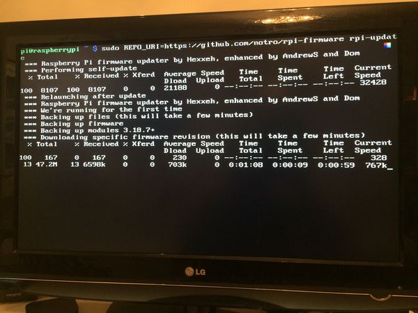 Raspberry Pi firmware being upgraded to include the fbtft drivers
Now we should have all the drivers we need, so let's look at a GitHub issue we found discussing this exact same device, looks like someone else has a better DVD drive and has already posted logs from the official drivers, which is almost all we need to get the LCD running.
    fbtft_request_gpios: 'reset' =GPIO025
    fbtft_request_gpios: 'dc' =GPIO024
    flexfb_verify_gpios_dc()
    fbtft_init_display()
    fbtft_reset()
    init: write(0xB0) 0x00
    init: write(0x11)
    init: mdelay(250)
    init: write(0x3A) 0x55
    init: write(0xC2) 0x44
    init: write(0xC5) 0x00 0x00 0x00 0x00
    init: write(0xE0) 0x0F 0x1F 0x1C 0x0C 0x0F 0x08 0x48 0x98 0x37 0x0A 0x13 0x04 0x11 0x0D 0x00
    init: write(0xE1) 0x0F 0X32 0x2E 0x0B 0x0D 0x05 0x47 0x75 0x37 0x06 0x10 0x03 0x24 0x20 0x00
    init: write(0xE2) 0x0F 0X32 0x2E 0x0B 0x0D 0x05 0x47 0x75 0x37 0x06 0x10 0x03 0x24 0x20 0x00
    init: write(0x36) 0x28
    init: write(0x11)
    init: write(0x29)
    Display update: 1691kB/s (177.354ms),fps=0 (0.000 ms)
    fbtft_register_backlight()
    fbtft_register_backlight(): led pin not set, exiting
    graphics fb1: flexb frame buffer, 480x320, 300kiB video memory, 4 kiB DMA buffer memory, fps=20, spi0.0 at 16MHz
    fbtft_device: spidev spi0.1 500kHZ 8 bits mode=0x00
    fbtft_device: flexfb spi0.0 16000kHZ 8 bits mode=0x00
    ads7846_device: Deleting spi0.1
    ads7846 spi0.1: touchscreen, irq 187
    input ADS7846 Touchscreen as /devices/platform/bcm2708_spi.0/spi_master/spi0/spi0.1/input/input1
This may seem cryptic, but when you look at it for a while it it's telling you quite many things. First, the GPIO pins for reset and dc (data command) are detected to be 25 and 24 respectively. Second, initializing the screen requires 11 writes with one 250ms delay in the middle. Third, the screen has resolution of 480x320 with 20fps frame rate and 16000kHz data transfer rate, no programmable backlight and it is located on SPI bus 0 chip 0. Fourth, we have a touchscreen on SPI bus 0 chip 1 with transfer rate of 500kHz.
One information missing from that log is the regwidth, which some of our friends on GitHub have already found out to be 16 bits. The flexfb driver supports giving custom init sequences as an array by using -1 for write command, -2 for delay and -3 for end of init sequence. Therefore on the console we can try the following:
    pi@raspberrypi ~ $ sudo modprobe flexfb nobacklight regwidth=16 init=-1,0xb0,0x0,-1,0x11,-2,250,-1,0x3A,0x55,-1,0xC2,0x44,-1,0xC5,0x00,0x00,0x00,0x00,-1,0xE0,0x0F,0x1F,0x1C,0x0C,0x0F,0x08,0x48,0x98,0x37,0x0A,0x13,0x04,0x11,0x0D,0x00,-1,0xE1,0x0F,0x32,0x2E,0x0B,0x0D,0x05,0x47,0x75,0x37,0x06,0x10,0x03,0x24,0x20,0x00,-1,0xE2,0x0F,0x32,0x2E,0x0B,0x0D,0x05,0x47,0x75,0x37,0x06,0x10,0x03,0x24,0x20,0x00,-1,0x36,0x28,-1,0x11,-1,0x29,-3 width=480 height=320
    pi@raspberrypi ~ $ sudo modprobe fbtft_device name=flexfb speed=16000000 gpios=reset:25,dc:24
    ERROR: could not insert 'fbtft_device': Invalid argument
Ok, that didn't work quite as expected, our arguments should all be valid so where is this invalid argument coming from? Easiest is to check from dmesg which prints the kernel log:
    pi@raspberrypi ~ $ dmesg | tail
    [   10.945412] EXT4-fs (mmcblk0p2): re-mounted. Opts: (null)
    [   11.483292] EXT4-fs (mmcblk0p2): re-mounted. Opts: (null)
    [   22.020254] smsc95xx 1-1.1:1.0 eth0: hardware isn't capable of remote wakeup
    [   23.609241] smsc95xx 1-1.1:1.0 eth0: link up, 100Mbps, full-duplex, lpa 0xCDE1
    [   29.310875] Adding 102396k swap on /var/swap.  Priority:-1 extents:2 across:2134012k SSFS
    [  216.893064] fbtft_device:  SPI devices registered:
    [  216.893106] fbtft_device:  'fb' Platform devices registered:
    [  216.893152] fbtft_device:      bcm2708_fb id=-1 pdata? no
    [  216.893214] fbtft_device:  spi_busnum_to_master(0) returned NULL
    [  216.893226] fbtft_device: failed to register SPI device
As we already have found out, our device uses SPI, which is a standard for communicating with peripherals quite common in embedded systems, for communication between the main system and the LCD. There is a kernel module for SPI, but it is not enabled by default, so we have to go back to raspi-config and enable it.
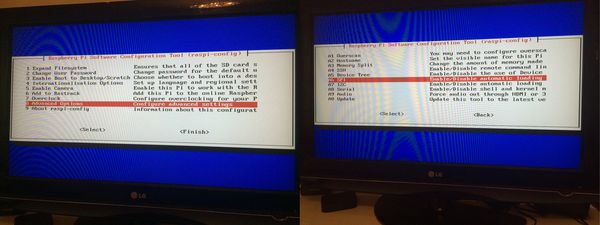 Enabling SPI driver in the raspi-config settings
The raspi-config suggests that we reboot now and we can do that. After reboot if we run the two modprobes again, something magical happens! The screen turns from white to black. It is possible that the screen is already working, but we need some way to prove it. Luckily there is this great command called con2fbmap, which can be used to map our console to another framebuffer. So if we simply try out con2fbmap 1 1 it should map our main console to the first framebuffer, and it does! We can change back to HDMI output by simply writing con2fbmap 1 0, and the console moves back there magically.
Being quite confident that everything is now in order, we have to make these changes persistent over reboots. To do that we will add the following two lines to the system configuration by using sudo nano /etc/modules:
    flexfb regwidth=16 nobacklight init=-1,0xb0,0x0,-1,0x11,-2,250,-1,0x3A,0x55,-1,0xC2,0x44,-1,0xC5,0x00,0x00,0x00,0x00,-1,0xE0,0x0F,0x1F,0x1C,0x0C,0x0F,0x08,0x48,0x98,0x37,0x0A,0x13,0x04,0x11,0x0D,0x00,-1,0xE1,0x0F,0x32,0x2E,0x0B,0x0D,0x05,0x47,0x75,0x37,0x06,0x10,0x03,0x24,0x20,0x00,-1,0xE2,0x0F,0x32,0x2E,0x0B,0x0D,0x05,0x47,0x75,0x37,0x06,0x10,0x03,0x24,0x20,0x00,-1,0x36,0x28,-1,0x11,-1,0x29,-3 width=480 height=320
    fbtft_device name=flexfb speed=16000000 gpios=reset:25,dc:24
Now it should be ok to reboot and make sure that the screen still turns black on boot. In our case we also want to get rid of the huge TV set, so we want to make the LCD screen the default screen for the system. On Linux the console and graphical environment work a bit differently. Our old screen is in fb0 and our new screen is in fb1, so to move the system console to our new screen we write sudo nano /boot/cmdline.txt and to the end of the line add the arguments fbcon=map:1 fbcon=font:ProFont6x11. The first argument maps the console to fb1 and the second argument changes the font to a smaller one (6x11 pixels).
It is possible to move the graphical environment to fb1 as well by sudo nano /usr/share/X11/xorg.conf.d/99-fbturbo.conf and simply changing the fb0 entry to fb1. For the changes to take effect we need to restart the graphical environment. Since we have made quite many changes, it's easier to just reboot the whole device and see everything moved to the LCD screen instead of the HDMI output.
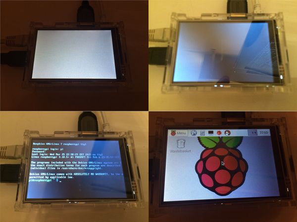 After the boot, after successful modprobe, after con2fbmap, and finally after the reboot
Touch Me Like You Do
Now the screen is in perfect order, but as we still remember it also has touch capabilities. There is a ads7846 module in the system, but we need to give it the correct parameters and load it. This can be done with the device tree overlay functionality of the firmware.
Our friends on GitHub again already found out that the penirq interrupt value should be 17, so we need to give some parameters to the kernel by using sudo nano /boot/config.txt and adding line:
dtoverlay=ads7846,speed=500000,penirq=17After reboot we do get the touch screen working ok, but things don't seem quite right. If we move it horizontally it actually moves vertically and vice versa. And it looks like the locations are not quite correct either. Actually for touch input we need to be able to calibrate three things correctly:
- X and Y axis need to be correct for the screen orientation
- Both X and Y axis need to have minimum and maximum range defined
- Both X and Y axis need to work to the correct direction
Because horizontal movement moves the mouse vertically and vice versa, we clearly have problems with step 1. This means that even though our screen is in landscape mode, the touch screen is actually in portrait mode and has the x and y axis swapped. So we should modify the config.txt parameters as follows:
dtoverlay=ads7846,speed=500000,penirq=17,swapxy=1After rebooting again this helps a bit and the y coordinate is about right but a bit in the wrong location, and the x coordinate moves left when we try to move right and vice versa, these are the problems 2 and 3 above. To make things easier we skip a few steps (more about that in the end of this post) and simply use sudo nano /usr/share/X11/xorg.conf.d/99-calibration.conf to copypaste the following to the new file:
    Section "InputClass"
        Identifier    "calibration"
        MatchProduct    "ADS7846 Touchscreen"
        Option    "Calibration"    "3900 240 240 3900"
    EndSection
Now you may ask, what are these magic numbers in calibration and what do they do? Well, the numbers are simply values "min_x max_x min_y max_y" in that order. They are device specific values that define the minimum and maximum values coming from the touch screen. You might remember that our x coordinates were wrong, but since here max_x is larger than min_x the system uses that information to automatically invert the x coordinates and that's why everything works.
After reboot we try to use the stylus to open a browser and keyboard to navigate to some website. Finally our touch screen works perfectly and the touch events go to the right spot!
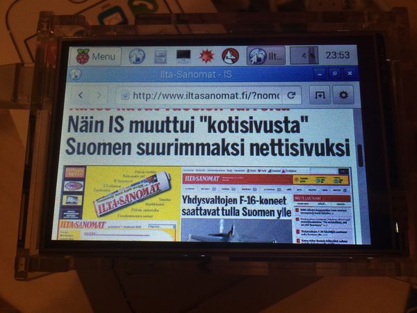 Reading our favourite newspaper with the touch screen
Turn Around, Bright Eyes
Our screen is now always in landscape mode, we might want to turn it around to portrait mode. And once again our friends on GitHub already realized that by modifying the -1,0x36,0x28 sequence in init we can turn the screen around, more specifically we need to edit the 0x28 byte. Problem with editing this is that it will also change the screen resolution and the touch screen x and y axes configuration. Through several experiments I have collected the correct parameter combinations below:
      init  width  height  swapxy  calibration
      0x28    480     320       1  "3900 240 240 3900"
      0x48    320     480       0  "3900 240 3900 240"
      0x88    320     480       0  "240 3900 240 3900"
      0xE8    480     320       1  "240 3900 3900 240"
To use them you need to modify the byte in init, change width and height arguments accordingly, change swap_xy argument for the touch screen, and finally edit touch screen calibration in /usr/share/X11/xorg.conf.d/99-calibration.conf. We decide to try the second to last line, which is in fact the native mode of our touch screen input, since its calibration has no x or y axis swapped. Discussions on GitHub suggest that some other people with the same device have small variations in the touch screen calibration. After reboot our device screen has turned 90 degrees and still looks nice.
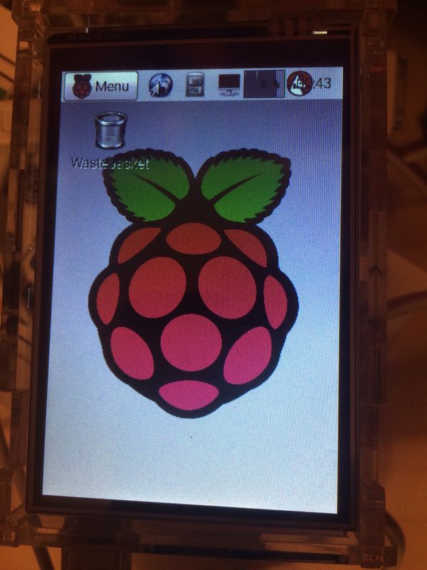 Portrait mode in action, a bit too narrow for the status bar.
Show Me Your Magic
We have talked about the calibration of the touch screen a lot and have used some numbers, but you might want to know where those numbers are coming from. The answer is quite simple, there's a very useful tool called xinput_calibrator that can do the calibration for us. These instructions assume we have the graphical environment running and are commanding the system either through SSH connection or in a console window.
The problem with xinput_calibrator is that it's only available in Debian testing (jessie) and our Raspbian distro is based on older Debian stable (wheezy). There are some binaries lying around, but personally I don't like to trust random binaries, so I simply compiled the xinput_calibrator myself:
    sudo apt-get install libx11-dev libxext-dev libxi-dev x11proto-input-dev
    wget http://github.com/downloads/tias/xinput_calibrator/xinput_calibrator-0.7.5.tar.gz
    tar xzvf xinput_calibrator-0.7.5.tar.gz
    cd xinput_calibrator-0.7.5/
    ./configure
    make
    sudo make install
We now have a xinput_calibrator installed under our /usr/local/ directory. Then we can simply run it and see what happens, first here is an example console output:
    pi@raspberrypi ~ $ DISPLAY=":0.0" /usr/local/bin/xinput_calibrator
    Calibrating EVDEV driver for "ADS7846 Touchscreen" id=8
        current calibration values (from XInput): min_x=0, max_x=4095 and min_y=0, max_y=4095

    Doing dynamic recalibration:
        Setting new calibration data: 3900, 240, 240, 3900


    --> Making the calibration permanent <--
      copy the snippet below into '/etc/X11/xorg.conf.d/99-calibration.conf'
    Section "InputClass"
        Identifier    "calibration"
        MatchProduct    "ADS7846 Touchscreen"
        Option    "Calibration"    "3900 240 240 3900"
    EndSection
And below is what it looks like on the screen.
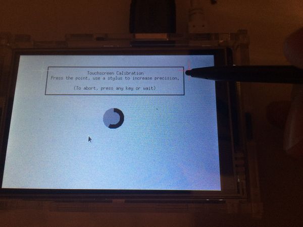 Calibration of the touch screen with stylus
So one simply has to click on the crosshairs on the screen and the application will print a correct configuration to the console. One important thing to notice is that the given path /etc/X11/xorg.conf.d/99-calibration.conf is not correct on Raspbian and the earlier mentioned /usr/share/X11/xorg.conf.d/99-calibration.conf should be used instead.
That's all Folks!
All text and images in this post are licensed under CC BY 4.0 license, feel free to distribute.
 Juho Vähä-HerttuaSenior Software Engineer